Background
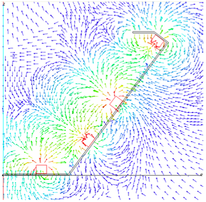
This work is an ongoing study of plasma losses to the magnetic cusps in multipole ion sources. Such sources are used in electrostatic gridded ion thrusters to improve plasma density and increase efficiency and performance in the ion thruster discharge chamber. In multipole ion sources, plasma is lost to the anode at a thin line of collection along the center of each magnet ring. The magnetic circuit is therefore responsible for the effective loss area of the source, which in turn controls discharge ionization performance, efficiency, and stability.

In this work we attempt to quantify the effective loss area to the magnetic cusp through a wide variety of experimental measurements including plasma potential and current density measurements at and in the region above the magnet surface as well as thoroughly characterizing the magnetic field at the magnet surface. The effective loss area is an important parameter in predictive models, and minimizing this area is key to improving source performance and efficiency.
Work Completed to Date
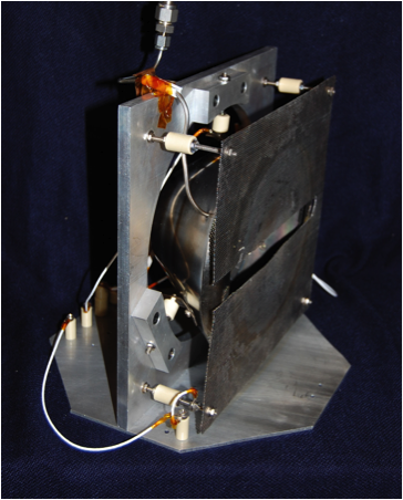
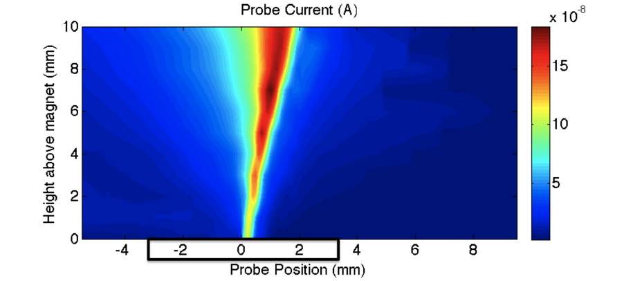
A 20-cm diameter, semi-conic discharge chamber was developed for initial testing1. It features four samarium-cobalt permanent magnet rings. Electrons are supplied via thermionic emission from a tungsten filament. Previous work used a planar Langmuir probe affixed to a 3-axis motion control system to map primary electron current density in the cusp region2,3. Primary electrons (electrons emitted directly from the cathode) are extremely important in that they are ultimately responsible for all ionization in the chamber. The longer a primary electron is confined in the chamber, the more ionizing events it will undergo and the more efficient the source will be.


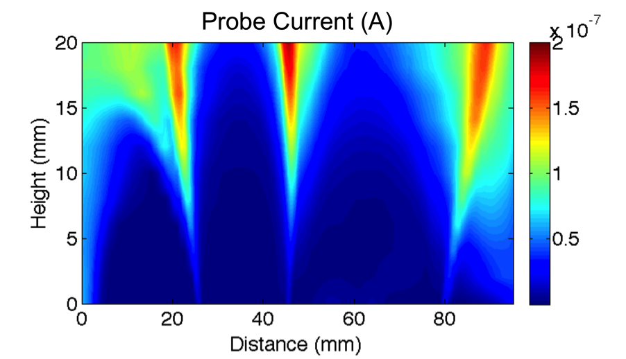
Primary electron current density was also mapped in the region above a steel plate featuring three permanent magnet line cusps in order to study the effects of source geometry and filament location on primary electron collection3.

Future Work
Future work will focus on making emissive and collecting probe measurements in the cusp region in such a way as to not disrupt the plasma sheath. This will enable more accurate efforts in quantifying plasma losses in the cusp region. The results of the experimental efforts will be incorporated into pre-existing predictive models.
Papers and Publications
1. Hubble, A. and Foster, J., “Plasma collection width measurements in a 10-cm ring cusp discharge chamber,” Proceedings of the 44th AIAA/ASM/SAE/ASEE Joint Propulsion Conference, Hartford, AIAA Paper 2008-4639.
2. Hubble, A.A. and Foster, J.E. “Primary Electron Transport and Losses in a Ring-Cusp Discharge Chamber,” Proceedings of the 31st International Electric Propulsion Conference, Ann Arbor, IEPC-2009-156 (2009).
3. Hubble, A.A. and Foster, J.E. “Spatially Resolved Study of Inter-Cusp Transport and Containment of Primary Electrons,” Proceedings of the 46th Joint Propulsion Conference, Nashville, AIAA-2010-7110 (2010).
